
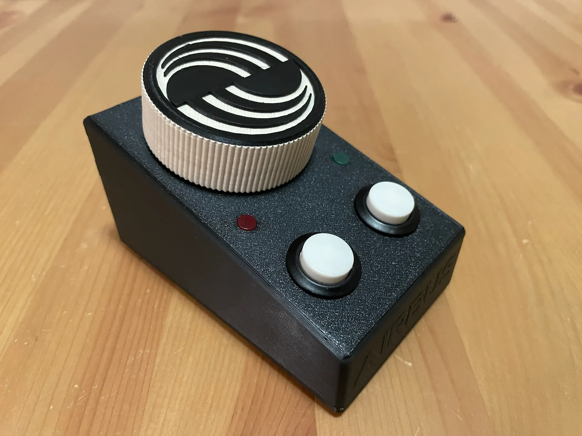
Airbus A320 Steering Tiller desktop edition
I built few full scale tillers but they are not very comfortable to use on small desks! So I decided to build another, smaller one! It is working with Microsoft Flight Simulator 2020 (tested) or probably with any other simulator (X-Plane, Prepar3D) on the market because device is recognized as standard gaming device in operating sytem with one axis and two buttons. LEDs are controlled with Arduino code directly.
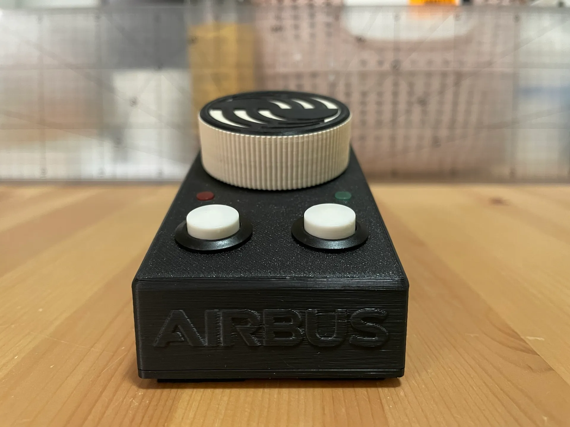
This one is using double, high quality dust proof potentiometer with center detent so it is reliable and long life. LEDs are designed to indicate which side the tiller is turned to. The colored diodes match the lighting on the plane. Red on the left and green on the right. One button can be used as a pedal disconnect (for flight control check during taxi) and second one can be used as a brake (if you are missing pedals with brakes).
No screws are needed, the case is snap-on and it is possible to add a balast and non-slip self-adhesive pads for better stability on the table.
The price of all components including PLA material is up to 20 USD.
And even though I have plenty of space on my desk, my favourite tiller to use is this one! 🙂
Why do you need it?
The most noticeable change is that steering with the rudder on the ground will only turn the nose wheel up to 6° which will not be sufficient for normal taxi operations and most turns. Tiller can turn the nose wheel up to 75° in either direction.
Parts needed:
- Arduino Pro Micro:
- ATmega32U4, 5V/16MHz
- Rotary potentiometer with center detent:
- ALPS RK09L1220 10KBX2CC 0.05 W 10 kΩ
- Momentary button for 16mm mounting hole
- R13-507 OFF-(ON) 250V/3A:
- Flat diffuse Light Emitting Diodes (LED):
- Green and red
- Resistors:
- 220Ω 0,5W
- Non-slip self-adhesive pads:
- You can buy them in any home goods store or on Amazon
- USB cable:
- USB-A to micro USB-B
Tools needed:
Standard equipment for soldering (soldering iron, tin, rosin and some wires (ideally silicone). Multimeter can be useful to check resistors, contacts and switches.
Filament:
PLA is fine. But you can use any filament you want. All non-flex materials will be ok. Regarding color, I am using black and white because it is color of my other computer accessories like keyboard, mouse and headphones. If you want color similar to Airbus or to famous Thrustmaster TCA hardware, you can use colorfabb blue/grey PLA filament or you can postproces with airbrush and RAL 5024 color.
Print settings:
You can print with any standard settings with supports. Only base should be printed without supports. But my recomendation is to use 100% infill to increase weight and stiffnes. It is not too much of material. It is just small box with knob.
Case should be printed on textured PEI powder-coated spring steel sheet to get nice texture on the top of the case. Rest can be printed on standard smooth spring steel sheet.
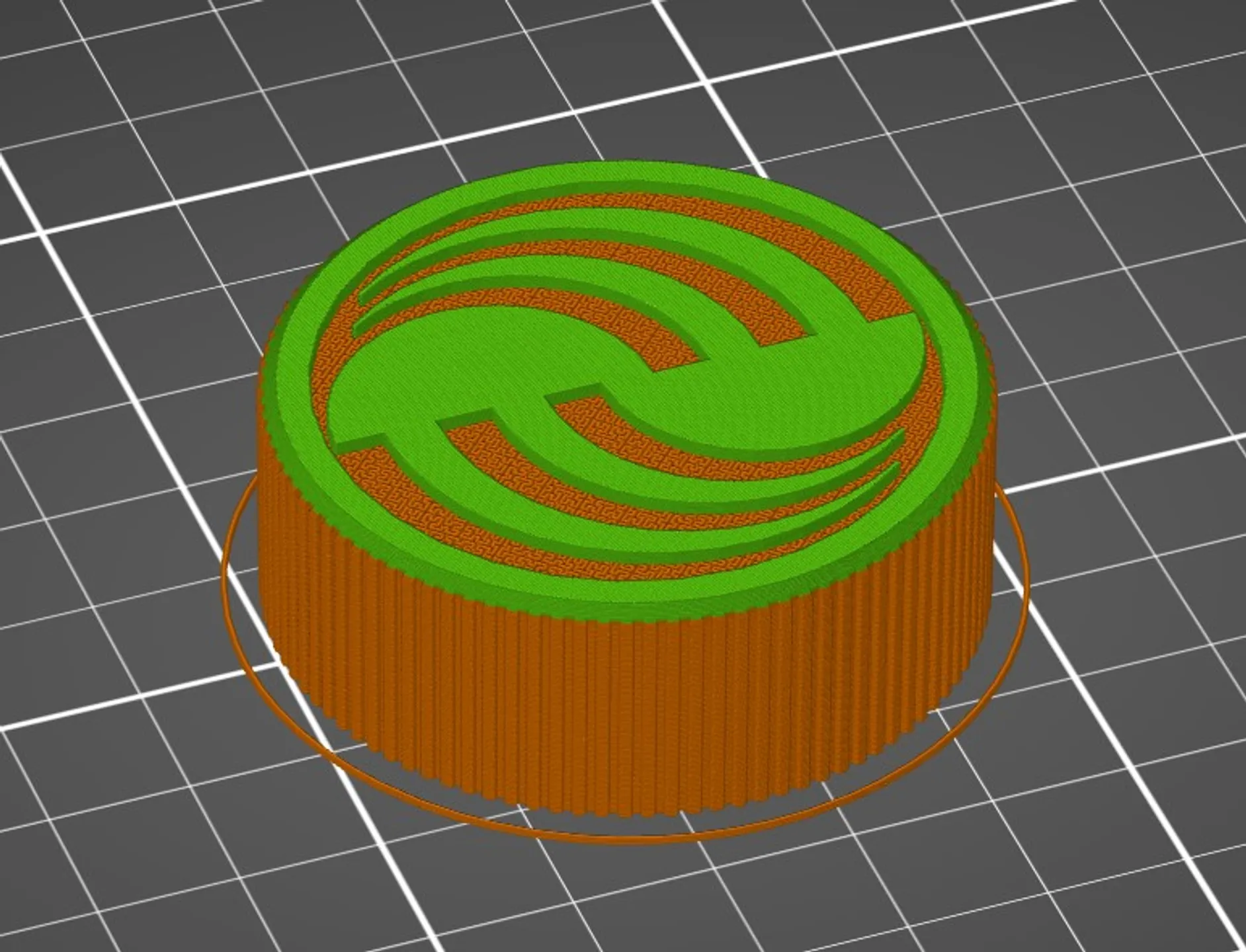
Knob with Airbus logo can be printed with hilbert curve and color change (2 parts), with color change (1 part) or without any special settings as one part.
You can use 3MF project files to slice with predefined settings. It is useful especially for the knob, so you dont have to set all settings manually, even if it is not complicated.
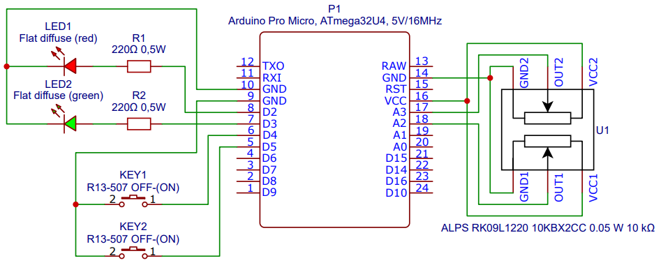
Wiring:
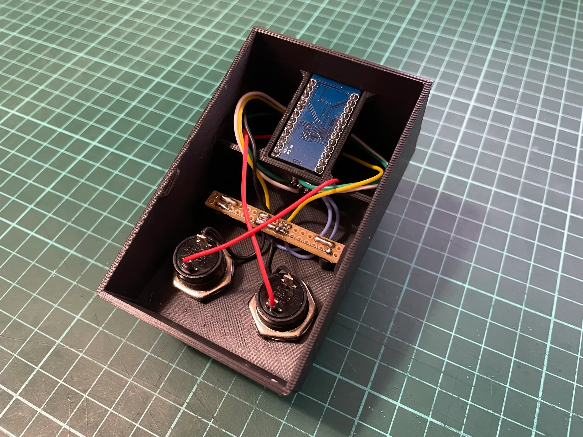
Please use high quality wires with silicon insulation because wires with plastic insulation will melt. Diameter 28AWG is fine. You can also use universal PCB for ground and LED wiring (you can see it on the pictures). But it is not necessary, everything can be wired with wires only. It is also possible to use DuPont pins on Arduino (there is enough space in the case) but you have to crimp connectors on to your wires. I am using them becuase it is easy to debug and develop new extensions (please see “Ideas and To Dos” section). For final product is ok to solder wires directly to the Arduino.
Wiring diagram:
Code:
Code was inspired by 2 similar projects from Github (links are in “Inspiration” section).
Ideas and To Dos:
- Add a sliding switch to the side to allow media control with knob (volume) and buttons (play/pause, mute).
- Add few side buttons to allow assign other functions for example like “TO check” or “MAX brake”.
- Cleanup the code. It is big mess right now.
FAQ & Tips:
- Arduino Pro Micro can be mounted with help of hot glue on the sides or with zip tie.
- Arduino Pro Micro with 3.3V/8MHz cant be used.
- Do not use clear or non-diffuse LEDs, they are too bright.
- If knob is too tight for your potentiometer, try increase size by few % and print again.
Tested and fully working with:
- Microsoft Flight Simulator 2020
- A32NX for MSFS by FlyByWire
- (please follow „Nose Wheel and Tiller Operation“ guide)
- A320 by Fenix Simulations
- Asobo ATR 42/72-600
- any other plane using standard axis for steering…
- A32NX for MSFS by FlyByWire
- X-Plane
Inspiration:
- GitHub – laubfrosch42/SteeringTiller: Steering-Tiller-Joystick for Flight Simulation
- GitHub – hotbso/tiller: Arduino based tiller for flight simulation
- Foot Powered Push To Talk Button by TinyBoat – Thingiverse